3 Weeks Remaining: Small Scale Prototype Wayside, Mechanism and Power Consumption
I. ULTRACAPACITORS
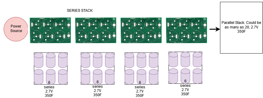
1. Series Balancing
1. Series Balancing
Most modular way to balance UCAPs in our opinion is to use predefined PCBs.
https://www.ebay.com/itm/Six-In-Series-MaxWell-350F-2-7V-T11-T10-Supercapacitor-Balance-Protection-Board/263928360582?epid=1950825530&hash=item3d735b2e86:g:g-sAAOSwqrZa1pLZ:rk:2:pf:0
HOW TO USE THEM: https://www.youtube.com/watch?v=MdqJcrDiKN4&t=799s2
https://www.ebay.com/itm/Six-In-Series-MaxWell-350F-2-7V-T11-T10-Supercapacitor-Balance-Protection-Board/263928360582?epid=1950825530&hash=item3d735b2e86:g:g-sAAOSwqrZa1pLZ:rk:2:pf:0
HOW TO USE THEM: https://www.youtube.com/watch?v=MdqJcrDiKN4&t=799s2
These
devices limit the voltage and balance each capacitor. These PCBs can be
combined to make a circuit with a combination of series and parallel:
2. MOSFET Charging
Using MOSFETs to control the source current. We can quickly charge the UCAP bank within the confines of the maximum current ratings. When the voltage reaches 2.65V, the current will be controlled down to roughly 1A to allow the balancing PCBs to work and to prevent overcharging.

a. Measuring Voltage across each UCAP
The individual monitoring of each UCAP is essential in making sure it does not over charge. Measuring the voltage using an extended analog input such as the Mux Shield II (http://mayhewlabs.com/products/mux-shield-2)The individual monitoring of each UCAP is essential in
making sure it does not over charge. Measuring the voltage using an
extended analog input such as the Mux Shield II
(http://mayhewlabs.com/products/mux-shield-2).
b. Measuring UCAP Input Current
Using a high current sensing device designed to output 0-5V to a micro-controller, we can read the initial and continuous current draw from the solar panels to the UCAPs. YouTube videos on how to do this: 1. https://www.youtube.com/watch?v=UF5jrnXvTlM 2. https://www.youtube.com/watch?v=lisprJs5sNU.
30A Hall Effect Current sensor:
c. Sending PWM signal to charging MOSFET based on current and voltage readings.
With
an initial current read, the micro controller can send a PWM signal to a
MOSFET and control the current into the UCAPs which creates a constant
current charger. Allowing maximum continuous current into the UCAPs until the voltage exceeds the limit is necessary to charge as fast as possible. This technique will be applied to both UCAP banks.
II. Mechanism CAD


We have assumed that the longest part of the mechanism have the least factor of safety (right figure). This could be solved by increasing the thickness of the part, by reducing the overall length or changing material composition.
Revised model might look like this to accomplished better Factor of Safety


III. Force Calculations and Power Consumption Graph


Comments
Post a Comment